(This article was first emailed on July 12th, 2021 to fans who had registered an interest in finding out more about our Tricorder.)
Using the tricorder created a conflict between the needs of the two crews on Desilu Studios’ Stage 9. Any member of the Enterprise crew lucky enough to have been issued with a tricorder would have expected to at least be able to look at the screen to check what important output was being displayed. The Desilu crew, however, had other ideas – they wanted to show off the detail of this high-tech hand-held equipment to the viewer. In most cases, the film crew got their way. As a result, the tricorder was often held with the hood open, the screen pointing horizontally, but weirdly, away from the user, ensuring that the viewer knew for certain that the crewmember was holding a miniature portable computer, even if they didn’t actually know how to use it.
Nowadays we are used to our TV show characters looking intently at their little portable computers while all we can see is the usually featureless back of the casing. Along with the directors, we have learned the visual shorthand – the character’s faces glow and eyes glint in reflected screen light. Occasionally, the scene cuts to an over-the-shoulder view of the screen, if needed to confirm some plot-critical information. However, in the 1960s a small handheld computer was an unknown quantity and, in Star Trek, a new and significant piece of sci-fi prop magic, so it needed presenting to the audience in a way that fully showed it off, but neither the technology nor the budget favoured close-up action shots of the tricorder’s screen. In the majority of scenes where the tricorder is in play, it’s ironic that it’s mainly the technophobic McCoy who manages to hold it correctly, allowing us to imagine what he is studying – in our mind’s eye, perhaps a miniaturised version of his large flat-screen sickbay monitor back on the Enterprise.

Often held the wrong way round by a crew that should have known better, to meet the needs of the other crew that should have really known better. Leave it to Dr. Mulhall, Sulu, Bones, and the Captain to show us how a miniature computer with a screen will actually be used in the future.
Occasionally, scenes show the tricorder’s hood rotating past the more typical front-facing one hundred degrees into a position that, when looked down upon from above, would actually make much more sense for a piece of kit hanging off a crew member’s shoulder. Despite the comparatively few times the tricorder is shown like that, this fully-rotated functionality is a properly prophetic look at how real scientists and engineers would learn to interact with heavy hand-held data-capture equipment carried by a strap. As such, we couldn’t ignore this aspect of the tricorder’s mechanical function. Early in the design process, we wanted to make sure our hood could rotate as close to 180˚ as possible.
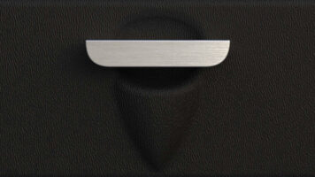
Hinge bearing
To ensure positive and accurate rotation, the tricorder’s hood assembly cannot rely purely on a tight fit and friction. Instead, the design of the hinge components incorporates sprung elements that can accommodate the minute variation that results when multiple parts are manufactured. This variation is called the tolerance stack-up and, as the tricorder’s hood needs to attach to and rotate inside an aluminium frame, this distribution of differing fits will mean that while some assemblies will be perfect, others could be too tight or too loose. In the case of the tricorder, a reasonably complex hinge bearing was needed.

CAD screen capture of hood showing rotation to maximum of 170˚.
Actually, the hinge bearing has four important functions and as a result, it is one of the key elements of the tricorder design, having both mechanical and aesthetic significance in the success of the finished product.
At the same time as accurately locating the hood and providing a positive, premium-feeling rotation, the hood bearing is also the protective guide for all the wires that need to pass through the metal side plate; it’s the sprung element for the detent mechanism; and it has features that locate the open-detection magnet securely in position. Added to that, with the requirement of being hidden in use, all these functions have to be focussed around a small hole only 10 mm in diameter (about one third of the area of a dime).

The hood hinge bearing pivot design is moulded in polyoxymethylene (POM): a tough, flexible, low-friction engineering plastic.

The bearing holds a tiny magnet as close as possible to the side of the hood, enabling hood-open detection.
With such an important structural component, material choice is crucial. The compact hood hinge bearing is moulded in polyoxymethylene (POM), a tough, flexible, low-friction engineering plastic. It securely locates into the side plate, the bush element of it protruding through the metal and into a matching hole in the side of the hood. A strong, flexible prong, designed to provide soft haptic clicks as the hood is rotated, also pokes through a hole in the metal plate and engages with 20 detent features that partially surround the hole on the side of the hood. The prong deforms outwards over each ridge as the hood is rotated, providing resistance that is accommodating of the tolerance stack-up in the assembly. The detents’ positioning ensures that the hood rotates all the way round evenly from closed to 170˚ in 10˚ steps. We considered having enlarged detents to preferentially halt the rotation at certain predetermined angles, but our research showed that there was no single exact position, and the final design allows the user to choose an open angle that they feel matches any one of the many open angles seen in the show. Three additional detents provide rotational control when the back is removed and the hood is able to rotate further round.
Depth
The 3D laser scans we took showed us that the original tricorder hood is about 10% shallower than had previously been thought. When compared with a modern mobile phone, the prop’s hood depth is a positively massive 23.25 mm (0.92”), however, for our development, we knew that it was not going to be easy to squeeze in everything we wanted to. Three PCBs, an LCD, a bundle of wires, screen glazing and a thick aluminium front panel soon eat up the available depth and required some clever thinking to make sure everything fitted, the fixing screws were hidden and that it could be moulded and assembled on the production line.

Three PCBs, an LCD, a bundle of wires (not shown here), screen glazing, and a thick aluminium front panel all have to fit inside the 23.25 mm deep hood.
Mould complexity
Injection moulding is an expensive upfront cost. Simple tools for flat or shallow unfeatured pieces are easy to design and easy to make. For something as complex as the tricorder hood, the tool itself is a complicated work of art and a triumph of modern manufacturing, made up of 207 precision components. To manage the cost, where possible, tricorder parts of a similar size have been buddied-up together into what are called family tools. In the case of the hood, it shares its tool with the battery compartment.

Just a few of the 207 parts that go to make up a single tool. Coloured to show the parts (black), core (gold), side action sliders (red), cavity (green).
Because the hood has features and holes that are (more or less) rotated at 90˚ to the axis of the tool’s opening action, the tool has to be designed to come apart like a three-dimensional jigsaw. The main shape of the hood is created between the core and the cavity, with the holes and features at each side of the hood created by moving parts of the tool that slide out of the way at the end of each moulding cycle so that the hood can be ejected. These hydraulically operated tool elements are called sliders and because they move from side to side, rather than in and out in the main direction of the tool, the tool is said to have a ‘side action’. As discussed before in our post #6, Cutting tools, these heavy tools have to be made with amazing precision to open and close thousands of times with watertight accuracy.

Close-up of hood and battery compartment family tool core. Coloured to show the parts (black), core (gold), side action sliders (red). The silver circles that can be seen in the gold core are the ejector pins that push the parts off the tool at the end of the moulding cycle.
(The hood tool is not the most complicated tricorder tool. That badge of honour goes to the fiendishly-complex disc partition tool, which requires five sliding parts.)
As you study the geometry of Wah Chang’s tricorder hood more closely, you begin to understand what a lovely part it is. For something made in the 1960s it has surprisingly mature curves that wouldn’t look out of place on a 2021 smart speaker. For the prop maker, creating the hood by thermoforming a patterned plastic sheet over a wooden buck is a neat trick used to make a thin-walled casing, but it’s not exactly rocket science (although, in this case, you might argue that it sort-of is). However, spin forward half a century and it’s easy to underestimate the enormity of the task of making it real. It’s hard to fully grasp how the technology, the range of incredible skills, the global infrastructure and international commercial cooperation, work so well together to make an electronics product like the tricorder possible.
LLAP
Chris

Coming next time
First shots – The mechanical build
Fans who register with us will be the first to read our news and the progress of this exciting Tricorder development and, later, where and when to purchase it. You can catch up with the story so far here on this blog, but if you haven’t already done so, why not register your interest in the Tricorder – you’ll then receive a personalised registration certificate and early access to these updates (before we publish them on our website).
Hi Chris,
I noticed that the hood has what appears to be a SD card access slot. Will the SD card contain the operating system/data or will it be blank and just for storing the user’s information?
Thanks,
Pat
We will release a more detailed update later about the SD card functionality, but basically, right now that is intended as a future-proofing feature of the design. System upgrades will be via the SD card. There will not be an SD card supplied with the tricorder at launch, but the tricorder itself will be capable of reading data from and writing data to the card. Depending on development bandwidth, that functionality may not be available in the launch product but will be able to be acquired by future firmware upgrades.
Hello TWC. Love the “First Shots” update.! I hope you produce a video of this Tricorder demonstrating some of the early function tests.
Thanks and we all can’t wait for this incredible replica!
jim
Hello Chris, Your design and development of the Tricorder is absolutely amazing. It is a delight to read every update. I hope to stick around long enough to purchase one of these incredible devices, being almost 7 decades old. The hard work of you and your team has given an old Star Trek fan some diversion from life’s complexities. My congratulations to you and your team. Best regards.
Hi Chris,
It is good to know that you are designing the Tricorder so that it can be updated when necessary. In update #12, you mention that you are able to update the software via the USB port. Is that only for development purposes or will the USB port, in the final product, be for more than just charging the battery? On a side note, the development screen image that is shown is more or less how I envisioned what the crew of the Enterprise was seeing when they were using the Tricorder.
Thanks for the updates.
Pat
Thanx for Trike Update #12. Informative as ever and continues to define the enormity of each step forward requiring any number preceding it. Consider my appetite remaining whetted. Who would think that a quick GIF of a diagnostic window could be so exciting—yet, there you have it. Chris says in the Update: “…the disc slips out, protruding by the perfect amount to grip it between thumb and forefinger in a way that I know will be repeated, over and over by every owner just for the fun of it.” I believe in his prophecy. Unless there is some external marking when the discs are racked, color coding will not be particularly useful until the discs are removed. I suppose that one could rely on memory, a chart, or even a display on the tricorder to know which disc to remove. Of course, it’s quite possible this has already been considered and I have found an impediment where none exists.
Best. Mike.
Loved the #12 update! My suggestion on the data disks is to make them Bluetooth or RFID ( like a FOB for a door system ) so the Tricorder can see them. The RFID idea can be tied to the operating system in seeing certain “data stores” for that disc. The Bluetooth, on the other hand, could be actual flash storage you can transfer info to from another Bluetooth device to get it into the Tricorder. I am not sure if the Bluetooth storage idea is available or small enough to fit into the size limitation of the disc as it is designed for the Tricorder. The Bluetooth would have to have a small inductive loop in it to power the data storage side to retrieve the data or a small battery.
Just a thought for you guys to think of. Please contact me if you want more info of my design ideas.
The #12 update was great! My suggestion on the data disks is to make them Bluetooth or RFID ( like a FOB for a door system ) so the Tricorder can see them. The RFID idea can be tied to the operating system in seeing certain “data stores” for that disc. The Bluetooth, on the other hand, could be actual flash storage you can transfer info to from another Bluetooth device to get it into the Tricorder. I am not sure if the Bluetooth storage idea is available or small enough to fit into the size limitation of the disc as it is designed for the Tricorder. The Bluetooth would have to have a small inductive loop in it to power the data storage side to retrieve the data or a small battery.
Just a thought for you guys to think of. Please contact me if you want more info of my design ideas.
Thanks for your thoughts and ideas. Actually, it is not trivial to make them Bluetooth or RFID, there are issues of powder, the fact that they are all next to each other, and that each one is surrounded by a (comparatively) large and thick rim of aluminium. We outline the disc functionality and describe our route to identifying the disc in the rightmost slot in any early blog post. You can read that here: https://www.thewandcompany.com/tricorder-update-7/. Thx
Thanks Chris for the response. I had read that article you mentioned, but thought maybe this might be an idea worth looking at. Again, fantastic job being done on the Tricorder. As an owner of the Phaser, Communicator and Phaser/Rock combo ( which I was happy to see that Phaser fit into the remote on place of the other unit ) and the David Tenant Sonic screwdriver remote, the quality is always there with your products.
When can I buy the Tricorder?
When we’re in production we’ll announce first to all those that have registered, and then to all other fans how it can be preordered.
I absolutely love this prop replica which I received a few days ago. The care and attention that has gone into the design and build is astonishing!
Currently my only (really minor) niggle is regarding the stiffness of the hood rotation hinge mechanism. If you open the hood to a “normal usage” position (screen facing towards the user, angled up at about 20-degrees or so from vertical) any attempt to press any of the buttons pushes the hood assembly further back before the button-action is triggered. The only way to use the buttons is to awkwardly hold the back of the hood steady with your hand while pressing, which seems counter-intuitive. Is this common, or is the hinge on my unit slacker than most?
Yes the use requires the user to put a finger behind the hood when using the buttons, but this is a replica of the prop and that had that “feature” also. We tried different detent stiffnesses and the stiffer detents made it feel wrong and very clumsy.
Just got mine yesterday and it is astonishing. Great build quality. I hope there will be the possibility in the future to add custom content, maybe even custom apps or custom discs. Definitely I’d like to see the medical scanner, as the compartment already has the dividers to make it fit.
great glad you like it. Right now it is not likely that we will make a medical scanner. There might be some form of app upgrade in the future, but we are busy with opur other projects now, so that is not likely in the short term, except for a couple of functional patch fixes that we intend to roll out soon.