
(This article was first emailed on July 26th, 2021 to fans who had registered an interest in finding out more about our Tricorder.)
The tricorder tools are finished well enough to test their function. The tools have been fitted to the relevant injection moulding machines and used for the first time to run off a set of trial parts; this step is called ‘first shots’.
As this project has moved through its development, our confidence that the tricorder really is moving out of fantasy and into reality has increased with each step. Even though each one of those steps have felt like major milestones, the practical leap to ‘first shots’ really is a genuine watershed. It is the first hard evidence that all the plans, the dreams, late nights, and hard work are actually coming together to create something solid, something real, something, dare I say it, good!

On display: the ‘first shots’ first fully assembled tricorder shows itself off in the classic tricorder stance.
Nothing can quite describe the feeling you get the first time you get your hands on an almost-production-ready version of the product you have been developing for so long. For the tricorder project, it’s a moment we’ve been looking forward to since the very first kick-off meeting, way back when. Again, the integrity of the design is apparent. Personally, I’m struck by how much more compact it is than I thought it was going to be, even though I have already held the 3D model – I think that is something to do with the combination of the size plus the finished weight and solidity of it. To me anyway, that combination certainly feels about perfect. Although not a technical term, the word that springs to mind is ‘meaty’… and it is satisfyingly so. It’s compactly weighty, without being over heavy, in a way that says its volume will be filled with tech promise. It feels tight and balanced. On the whole, even though these are first shots, it’s neat and accurately finished in a way that shouts real-world production kit.
The disc ejection mechanism works as expected. Push any disc about a quarter of an inch (5 mm) inwards with the tip of your thumb until a satisfying click tells you that the disc is ready to be ejected; release the pressure and the disc slips out, protruding by the perfect amount to grip it between thumb and forefinger in a way that I know will be repeated, over and over by every owner just for the fun of it.
Disc ejection: works well but disc centres will need some tool touch-up to add subtle geometry and a fraction more thickness, which will increase premium feel.
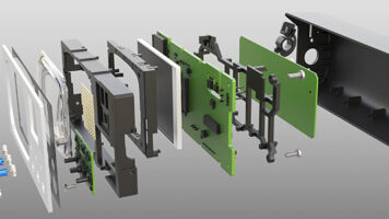
Changes can still be made at this stage, but they are typically (hopefully) limited to small adjustments: minor technical refinements to the fit and function of each part to improve how they work together. 3D printing can only take the design so far, as injection-moulded parts made in the correct materials behave differently – better, it is always hoped – obviously. With foresight, where possible, most of the parts have been designed so that where changes are required, the affected components only need to be made bigger in certain areas to refine the fit at critical points. When this is the case, the tool revisions are relatively simple, ‘metal-off’ changes, where only a small amount of machining is needed to make sure the moulded components fit together perfectly. For problems that go the other way, where the fit is too tight and less of a component is needed, then ‘metal-on’ changes are required. Metal-on changes are more difficult and time-consuming and, as the name implies, involve adding metal to the tool (by welding or fitting an insert into it) to enable further machining back to make the new revised cavity or core. As some degree of tooling modification is almost always required, this step is a planned-for stage of the project, typically referred to as ‘tool touch up’.

The back door’s inside relief pattern adds stiffness and, along with the electronics ‘glamour panel’, takes surface relief design cues from features found in the Enterprise engine room.
Main patterns and particular surface features that are part of the underlying design are included in the tooling, but at this stage the tool cavities haven’t been properly finished. They aren’t polished, plated or patterned with any fine surface textures, and won’t be until we are happy that the parts are just how we want them and performing exactly as they should.

The first mouldings to come out of the back door tool cavity. The Kydex texture for the external surface and a light EDM finish for the internal surface will be applied to the tool when we are happy with the fit and performance of them, and certain that the tool will not need any further metal-off or metal-on revisions.
The first shots are a big test of every part of the mechanical design and its translation to the production phase of the project. It’s also the injection moulding tooling’s first trial run which enables the moulding shop to see how the tool cavities perform and what minor adjustments of flow, cycle time and temperature profiles will need to be optimised in order to minimise any shrinkage and sink marks that will affect the mechanical performance and aesthetic appearance of the finished parts.

Finished enough for it to be functional, the tricorder door tool is taken to the moulding shop where it is fitted to an injection moulding machine to make the first real parts, or ‘first shots’.
As the different areas of the development are running concurrently, this is the first time that all the mechanical parts have been assembled together with the functioning electronics inside it. Making the jump from the bench rig into the production unit, with the proposed production chipset, is a critical move and allows the internal sensors to be tested in situ. It enables the electronics team to check if there are any unexpected issues when all the internal (and external) sensors are working with each other in the same vicinity. Factors that are difficult to replicate or accurately predict on the bench, such as thermal effects and component cross-talk, can be observed directly.

The first time the real parts have been assembled. The LCD displays a debugging diagnostic screen reporting internal sensor status. Even without the surface texture and the correct user interface graphics, it already looks ready for action.
To help the transition, a special development screen dynamically displays the status of the sensors on the LCD, and code has been written that allows the development software to be updated via the USB port, to avoid having to open the hood and dismantle the assembly to make software updates. The software is complex (for us, at least) and will require months of trials and study as it now moves towards the optimised production version.
The development screen, dynamically showing the various sensor values and other selected functions, is used for debugging and software optimisation. The screen glazing has been polished by hand as the unpolished injection moulding tooling produced a slightly hazy part.
After nearly three year’s work, as milestones go, ‘first shots’ is a biggie. Seeing the injection-moulded parts assembled together for the first time stirs some strong feelings in the hearts of engineers not normally known for getting emotional.
LLAP
Chris

Coming next time
Edith Keeler – Developing content
Fans who register with us will be the first to read our news and the progress of this exciting Tricorder development and, later, where and when to purchase it. You can catch up with the story so far here on this blog, but if you haven’t already done so, why not register your interest in the Tricorder – you’ll then receive a personalised registration certificate and early access to these updates (before we publish them on our website).
can’t wait I remember a few years back reaching out to you guys asking if you were going to do the tricorder so I have the phaser and communicator from you guys but the reply I was given about the tricorder was, no plans at this time. It was disappointing. Glad you guys are finishing it up. Starting to save money, my old lady says it’s foolish to spend money on toys for a grown man lol, many thanks
What price, happiness?
Congratulations on this achievement!
Please make it so regular folks can access that diagnostic screen, even if it takes a special keypress combination or something. It’s very cool looking. There are only going to be so many times that you’ll want to look at a still from a prop newspaper with Joan Collins, but a real working sensor screen would be awesome.
So looking forward to completing my landing party collection with one of these!
Don’t worry, there will be plenty of real dynamic status screens reporting the real-time sensor input. We will be discussing their function in future newsletter emails and blog posts. There’ll be lots of exciting functions.
I love you guys!!
Great job Chris, Richard and TWC team! You’re really going above and beyond, even what us fans were expecting. I hope you can post some videos of the different functions of the First Shots prototype.
Thanks again and keep up the great work.
jim
Any update? I haven’t received any for quite some time. Really looking forward to getting one!
You guys are a true class act!
I have your Communicator(2) and Phaser and they are works of art. Needless to say, I look forward to adding your Tricorder to complete the set.
Highest Regards,
Mark Myers
How much will it be sold for? When will it be for sale?
So excited, Wand Co. crew! Thank you for loving Trek as much as we do!!!
Thanx for the superior render of the display in this blog. I was starting to get a bit squinky-eyed with the earlier iterations. You must imagine how much we’re all looking forward to the amazing visuals to shoot out of your screen. Want it now, want it now, want it now. Best. Mike.
Will there be metric-to-English conversions for mathematically-challenged colonials? Best. Mike.
As Columbo would say, “and one more thing.” Please, let that blue object in the base be an owner-replaceable power cell. Best. Mike.
Indeed it is!
This latest product looks really terrific! I see on the rear of the Tricorder, there appears to be a USB port. Is that purely for charging purposes or to transfer data to a computer? If it’s only for charging, was there a reason you didn’t didn’t use inductive charging as was employed with the Communicator?
For now, the USB-C socket is for battery charging. However, we are building in the infrastructure for it to be potentially used for data transfer in the future. Creating that extra functionality is an extra development workload and we are working out if and when we can do it.
Charging via a cable is much more efficient than wireless charging. As well as requiring more electronics in the main device, wireless charging requires another device to provide the other side of the wireless charging circuit. This adds cost and complexity both to the development process and the end product. Wireless charging is also quite lossy and thus as is not as efficient as a cable. The wireless charging process generates waste heat which is not so good for the environment. So, right now, with current technology, where there is room for a cable and it is convenient to use one, a cable will always be a more cost-effective and more efficient method of charging or powering devices.
For the communicator, we actually considered both a charging cable and spring contacts, as well as wireless power transfer, for charging it. We could not see how we could fit a charging plug socket in the communicator housing that would not spoil its appearance or make it hard to display, more difficult to place on its cradle and lift it off quickly to take a call, and less reliable in use. In any case, it is quite crowded inside the communicator and at that scale, a charging plug socket is a large thing to fit in. So, for the communicator, wireless charging was practically the most appropriate and aesthetically pleasing solution.
This is AWESOME!!!
I remember years ago when Charlotte first remarked that a Tricorder was being ”talked about” and I told her how cool it would be if the screens from City on The Edge of Forever could be played on it. Edith’s picture at the end of this entry brought such a huge smile to my face that I knocked a lamp off my end table. (Think Dr Phlox). It seems that you and I are on some of the wavelengths. As I read each of these entries it makes me think of what a special thing it is for you and Richard to have been brought together to make all of these wonderful “toys”. Star Trek is in many ways a magic portal to the future and now you both together are helping us all to believe in magic again. So desperately needed today, so beautifully delivered by you both. Bravo!!! I warn you though, much more of this excitement and I will be forced to fly to England in order to look over your shoulders as you optimize software. Each Blog posting makes me a bit more apoplectic than the one before.
Yes, how could Edith Keeler not be part of our shared journey? Of course, if and when you make it over to the UK there is a cold lager or a warm beer waiting for you!
This project looks amazing…but considering the demand, what are you guys going to do to ensure scalpers don’t suck these things up in 20 seconds?
We are going to offer them to registered fans first and then gauge the number that needs to be made. Initially, we are not going to limit the preorders from each person but in order to accurately see how big the demand is we are going to probably ask for a deposit to stop people randomly putting their name down for more than they need for themselves.
Of course, for you folks, once you get your pre-order metric, the $64,000-question will be what multiplication factor is the correct one for your final assembly line? I can only assume that you’ve kept close track of such things with your other products and that will factor into your decision. I’m a business wonk at heart. Best. Mike.
This thing looks absolutely bonkers and those initial shots look phenomenal. You guys have outdone yourselves here. I’m really jonesing for one of those TOS-era phasers that’s now out of production, but depending on the price this thing actually looks a helluva lot more fun. Will there be an API and dev potential for people who want to upload their own software? I mean, since that’s a thing we can actually do with hardware like this nowadays, I think that’d be rad. I need to reroute some phase coils to the nadion emitter or something, and an API would make it easy for me to do that!
This seems to be the Science version. Any plans for the Medical or Geo versions?
I assume the answer is: It depends on the interest and demand for the first version.
Will you be including a handheld scanner which would normally be stored in the lower compartment? Or could this be available as a future add on option?
Will you be including a handheld scanner which would normally be stored in the lower compartment?
No we will not be including a hand scanner, but we are making sure the compartment fits a replica sized hand scanner
So with that being said does that mean we could be getting a geo or med scanner that connects via Bluetooth down the line
you know each one with a different sd card update LOL
Man…I was around when it aired in 1966 and saw it live, so this is a dream waiting for 50+ years. Cant wait for it!
I echo the bulk of comments here: frankly, better than anything I could ever have wished for. Superb!
So, the obvious follow-up & companion piece for this would be Bones’ “Twinkly Thingy” – what about it? Be even better if it could pair using BT LPP and interact with this beauty…
Rob, yes I know what you mean, But to do that nicely is another large piece of work. We have designed the internal spacers in the bottom compartment so that they can be moved about and set in a position so as to fit a medical scanner, but we don’t have any plans at the moment to supply that with the tricorder. Who knows though, that could possibly be something for the future or a great opportunity from some after-sales owner scratch building!
Absolutely superb! Commence this exciting project!… and let me buy one.
This is utterly amazing. I have toyed around and built a “breadboard tricorder”, meaning it is an Arduino and RasPi with many of the expected “tricorder” sensors and features on a breadboard, but never tried or even considered putting it in an enclosure. I can not wait for these to become available. Absolutely incredible work. How did you get the sensors in there to read external data without being influenced or impeded by the case? Also, I would love to see a Bluetooth hand scanner upgrade in the future. That would be the bomb. Perhaps it could carry a temp sensor?
I noticed a small “port’ on the back lower left corner; did I miss something in the articles about batter charger or is it a link to PC?
When is it coming out for purchase? We’ve been waiting a long time. The sooner the better. Ray
Is this dead ? Seems like it, been a very long time.
Is the wand co still in business? Bankruptcy?